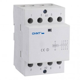
TeSys Telemecanique Contactor D 18A 3P 24VDC LC1D18BD
Schneider TeSys LC1D contactor with the following characteristics:
- Number of poles:3
- Rated operating voltage Ue:<= 690 V DC 25...400 Hz Power circuit - <= 300 VDC Power circuit
- Conventional thermal current in open air: 10 A at <60 °C for signaling circuit, 32 A at <60 °C for Power circuit
- Control circuit type: DC standards
- Auxiliary contact composition: 1 NO + 1 NC
- Coil technology with built-in suppression device
- Minimum switching voltage: 17V for signaling circuit
- Minimum switching current: 5mA per signaling circuit
- Rated impulse withstand voltage [Uimp]: 6 kV in accordance with IEC 60947

TeSys Telemecanique Contactor D 18A 3P 24VDC LC1D18BD
TeSys Telemecanique Contactor D 18A 3P 24VDC LC1D18BD
Tax included
TeSys Telemecanique Contactor D 18A 3P 24VDC LC1D18BD
Frequently bought together
LC1D18BD is a 3-pole TeSys D contactor from Schneider Electric for motor applications up to 7.5 kW at 400V.
It includes a 24V DC coil and integrated 1NA+1NC auxiliary contacts; it can be used in all control systems and safety applications due to its certified NC mirror contact. Compact, DIN-rail-mounted, it ensures high reliability and durability. Available worldwide, it is certified to various standards (IEC, UL, CSA, CCC, EAC, for use in marine environments) and is Green Premium (RoHS/REACH) compliant.
Benefits:
- Compact product, 45 mm wide, for DIN rail and panel mounting
- Separation between power and control circuits, easy front access to coil and auxiliary contact connections
- Equipped with a 24 V DC coil that can be powered at 50 Hz or 60 Hz
- Features 2 built-in 1NA+1NC auxiliary contacts
- High electrical durability, guaranteed for 2 million cycles at 18 A AC-3 440 V
- Environmentally friendly product performance
Rated use current:
- 18 A 60 °C) "AC" AC-3 for Power Circuit at <= 440 V
- 32 A 60 °C) "AC" AC-1 for Power Circuit at <= 440 V
- 18 A 60 °C) "AC" AC-3e for Power circuit at <= 440 V
Motor power KW:
- 4 kW at 220...230 V AC 50/60 Hz (AC-3)
- 7.5 kW at 380...400 V AC 50/60 Hz (AC-3)
- 9 kW at 415...440 V AC 50/60 Hz (AC-3)
- 10 kW at 500 V AC 50/60 Hz (AC-3)
- 10 kW at 660...690 V AC 50/60 Hz (AC-3)
- 4 kW at 400 V AC 50/60 Hz (AC-4)
- 4 kW at 220...230 V AC 50/60 Hz (AC-3e)
- 7.5 kW at 380...400 V AC 50/60 Hz (AC-3e)
- 9 kW at 415...440 V AC 50/60 Hz (AC-3e)
- 10 kW at 500 V AC 50/60 Hz (AC-3e)
- 10 kW at 660...690 V AC 50/60 Hz (AC-3e)
Motor power in hp:
- 1 hp at 115 V for 1 phase motorsCA 50/60 Hz
- 3 hp at 230/240 V for 1 phase motorsCA 50/60 Hz
- 5 hp at 200/208 V for 3 phase motorsCA 50/60 Hz
- 5 hp at 230/240 V for 3 phase motorsCA 50/60 Hz
- 10 hp at 460/480 V for 3 phase motorsCA 50/60 Hz
- 15 hp at 575/600 V for 3-phase motorsCA 50/60 Hz
Rated closing power Irms:
- 140 A "AC" for signaling circuit complying with IEC 60947-5-1
- 250 A DC for signaling circuit complying with IEC 60947-5-1
- 300 A at 440 V for power circuit complying with IEC 60947
Rated allowable short-circuit current (ICW):
- 145 A at <40 °C - 10 s for Power Circuit
- 240 A at <40 °C - 1 s for Power Circuit
- 40 A at <40 °C - 10 min per Power Circuit
- 84 A at <40 °C - 1 min per Power circuit
- 100 A - 1 s per signaling circuit
- 120 A - 500 ms per signaling circuit
- 140 A - 100 ms per signaling circuit
Associated fuse gauge:
- 10 A gG for signaling circuit complying with IEC 60947-5-1
- 50 A gG at <= 690 V Type 1 coordination for Power circuit
- 35 A gG at <= 690 V coordination Type 2 for Power circuit
Rated insulation voltage:
- 690 V complying with IEC 60947-4-1 Power Circuit
- 600 V CSA certified Power circuit
- 600 V UL certified Power circuit
- 690 V complying with IEC 60947-1 signaling circuit
- 600 V CSA certified signaling circuit
- 600 V UL certified signaling circuit
Mechanical robustness:
- Open contactor vibration (2 Gn, 5...300 Hz)
- Contactor vibration closed (4 Gn, 5...300 Hz)
- Contactor shocks open (10 Gn for 11 ms)
- Contactor shocks closed (15 Gn for 11 ms)
Connections / Terminals:
- Control circuit screw clamps: 1 1...4 mm² - cable stiffness: flexible without cable end
- Control circuit screw clamps: 2 1...4 mm² - cable stiffness: flexible without cable end
- Control circuit screw clamps: 1 1...4 mm² - cable stiffness: flexible with cable end
- Control circuit screw clamps: 2 1...2.5 mm² - cable stiffness: flexible with cable end
- Control circuit screw clamps: 1 1...4 mm² - cable stiffness: solid without cable end
- Control circuit screw clamps: 2 1...4 mm² - cable stiffness: solid without cable end
- Screw clamp terminals Power circuit: 1 1.5...6 mm² - cable stiffness: flexible without cable end
- Screw clamp terminals Power circuit: 2 1.5...6 mm² - cable stiffness: flexible without cable end
- Screw clamp terminals Power circuit: 1 1...6 mm² - cable stiffness: flexible with cable end
- Screw clamp terminals Power circuit: 2 1...4 mm² - cable stiffness: flexible with cable end
- Screw clamp terminals Power circuit: 1 1.5...6 mm² - cable stiffness: solid without cable end
- Screw clamp terminals Power circuit: 2 1.5...6 mm² - cable stiffness: solid without cable end
Tightening torque:
- Power circuit: 1.7 Nm - on screw clamps - with Ø 6 mm flat screwdriver
- Power circuit: 1.7 Nm - on screw clamping terminals - with Philips screwdriver No 2
- Control circuit: 1.7 Nm - on screw clamps - with Ø 6 mm flat screwdriver
- Control circuit: 1.7 Nm - on screw clamps - with Philips screwdriver No 2
- Control circuit: 1.7 Nm - on screw clamping terminals - with pozidriv screwdriver No 2
- Power circuit: 1.7 Nm - on screw clamps - with pozidriv screwdriver No 2
Other Features:
- Mechanical durability: 30 Mccycles
- Installation: Plate - Rail
- Safety Reliability Level: B10d = 1369863 cycles Contactor with rated load according to EN/ISO 13849-1 - B10d = 20000000 cycles Contactor with mechanical load according to EN/ISO 13849-1
- Control circuit voltage limits:0.1...0.25 Uc -40...70 °C de-energizing DC, 0.7...1.25 Uc -40...60 °C operating DC, 1...1.25 Uc 60...70 °C operating DC
- Inrush power in W:5.4 W 20 °C)
- Holding power consumption W: 5.4 W at 20 °C
- Operating time: 53.55...72.45 ms closing, 16...24 ms opening
- Time constant: 28 ms
- Maximum operating cycles: 3600 cycles/h at <60 °C
- Electrical life: 1.65 Mcicli 18 A AC-3 at Ue <= 440 V, 1 Mcicli 32 A AC-1 at Ue <= 440 V ,1.65 Mcicli 18 A AC-3e at Ue <= 440 V
- No-overlap time: 1.5 ms upon deactivation between NC and NO contact, 1.5 ms upon activation between NC and NO contact
- Auxiliary contact composition: 1 NO + 1 NC
- Auxiliary contact type: Mechanically linked type 1 NO + 1 NC complying with IEC 60947-5-1, mirror contact type 1 NC complying with IEC 60947-4-1
- Signaling circ. frequency: 25 to 400 Hz
- Protective treatment: TH in accordance with IEC 60068-2-30
- Climatic tightness: complies with IACS E10 moist heat exposure, complies with IEC 60947-1 Annex Q category D moist heat exposure
- Insulation resistance: > 10 MOhm per signaling circuit
- IP rating: IP20 Front side complies with IEC 60529
- Dimensions: height 77 mm - width 45 mm - depth 95 mm
- Allowable temperature near the device: -40/+60 °C, -60/+70 °C with derating
- Operating altitude: 0...3000 m
- Fire resistance: 850 °C complying with IEC 60695-2-1
- Fire resistance: V1 in accordance with UL 94
- Weight: 0.490 kg
Data sheet
- Type: Contactors
- Voltage: 24V
- Poles: 3P
- Degree of protection: IP20


 : 9
: 9


